Design tool lets novices do in minutes what would take experts in computer-aided design hours.
The technology behind 3-D printing is growing more and more common, but the ability to create designs for it is not. Any but the simplest designs require expertise with computer-aided design (CAD) applications, and even for the experts, the design process is immensely time consuming.
Researchers at MIT and the Interdisciplinary Center Herzliya in Israel aim to change that, with a new system that automatically turns CAD files into visual models that users can modify in real time, simply by moving virtual sliders on a Web page. Once the design meets the user’s specifications, he or she hits the print button to send it to a 3-D printer.
“We envision a world where everything you buy can potentially be customized, and technologies such as 3-D printing promise that that might be cost-effective,” says Masha Shugrina, an MIT graduate student in computer science and engineering and one of the new system’s designers. “So the question we set out to answer was, ‘How do you actually allow people to modify digital designs in a way that keeps them functional?’”
For a CAD user, modifying a design means changing numerical values in input fields and then waiting for as much as a minute while the program recalculates the geometry of the associated object.
Once the design is finalized, it has to be tested using simulation software. For designs intended for 3-D printers, compliance with the printers’ specifications is one such test. But designers typically test their designs for structural stability and integrity as well. Those tests can take anywhere from several minutes to several hours, and they need to be rerun every time the design changes.
Advance work
Shugrina and her collaborators — her thesis advisor, Wojciech Matusik, an associate professor of electrical engineering and computer science at MIT, and Ariel Shamir of IDC Herzliya — are trying to turn visual design into something novices can do in real time. They presented their new system, dubbed “Fab Forms,” at the Association for Computing Machinery’s Siggraph conference, in August.
Fab Forms begins with a design created by a seasoned CAD user. It then sweeps through a wide range of values for the design’s parameters — the numbers that a CAD user would typically change by hand — calculating the resulting geometries and storing them in a database.
For each of those geometries, the system also runs a battery of tests, specified by the designer, and it again stores the results. The whole process would take hundreds of hours on a single computer, but in their experiments, the researchers distributed the tasks among servers in the cloud.
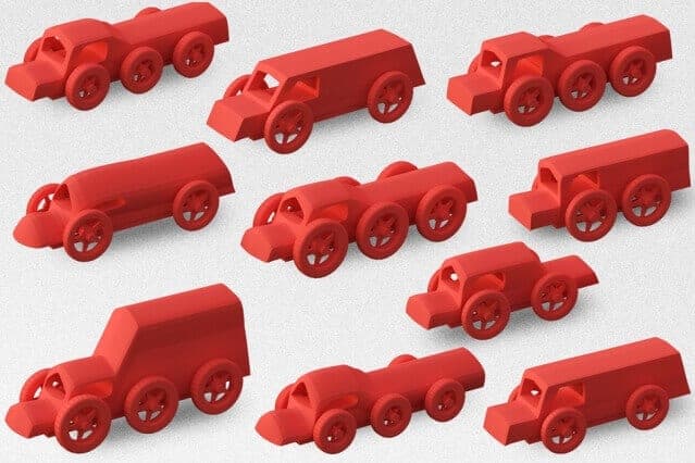
In their experiments, the researchers used eight designs, including a high-heeled shoe, a chess set, a toy car, and a coffee mug. The system samples enough values of the design parameters to offer a good approximation of all the available options, but that number varies from design to design. In some cases, it was only a few thousand samples, but in others it was hundreds of thousands. The researchers also developed some clever techniques to exploit similarities in design variations to compress the data, but the largest data set still took up 17 gigabytes of memory.
Intuitive interface
Finally, the system generates a user interface, a Web page that can be opened in an ordinary browser. The interface consists of a central window, which displays a 3-D model of an object, and a group of sliders, which vary the parameters of the object’s design. The system automatically weeds out all the parameter values that lead to unprintable or unstable designs, so the sliders are restricted to valid designs.
Moving one of the sliders — changing the height of the shoe’s heel, say, or the width of the mug’s base — sweeps through visual depictions of the associated geometries, presenting in real time what would take hours to calculate with a CAD program. “The sample density is high enough that it looks continuous to the user,” Matusik says.
If, however, a particularly sharp-eyed user wanted a value for a parameter that fell between two of the samples stored in the database, the system can call up the CAD program, calculate the associated geometry, and then run tests on it. That might take several minutes, but at that point, the user will have a good idea of what the final design should look like.
“Autodesk has simplified versions of this project,” says Ryan Schmidt, a senior principal research scientist and head of the Design and Fabrication Group at Autodesk Research, the research arm of the leading manufacturer of CAD software. “We have a thing called Project Shapeshifter that is very similar to what a lot of other people are doing right now, which is making these geometry generators that have a parametric model you can explore. But they all have this common problem: that you can very easily make something that won’t work on your printer. What I thought was super-exciting about this work is that it can prevent you from designing something that isn’t going to print or that isn’t going to be strong enough once you’ve printed it.”
“As soon as I saw the [Siggraph] talk, I sent it to the people who work on Shapeshifter and said, ‘You guys should have this,’” he adds. “The sliders are an interface to what they did, but the underlying technology actually has a much broader application, I think, than just this consumer product for CAD novices.”
If our reporting has informed or inspired you, please consider making a donation. Every contribution, no matter the size, empowers us to continue delivering accurate, engaging, and trustworthy science and medical news. Independent journalism requires time, effort, and resources—your support ensures we can keep uncovering the stories that matter most to you.
Join us in making knowledge accessible and impactful. Thank you for standing with us!

